



 Current Location: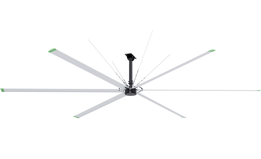


KPF7300 Series
- Diameter (m)
- 7.3
- Rated power consumption (W)
- 1500
- Number of fan blades
- 6
- Fan blade width
- 15500
- Fan blade width
- 189
- Sound
- 55dB(A)
- Fan blade material
- 6063-T5
- Voltage
- 380Vac
- Weight (kg)
- 110
- Environment
- Indoor
- Rated speed (rpm)
- 60
Product Description
1.1 Thank you very much for purchasing TORINDRIVE Fan permanent magnet brushless industrial fan!
We will provide you with the optimal solution for large-scale industrial fans. Our fans will provide you with a wider speed range, more energy-saving, and quieter user experience. Smaller and lighter motors will also provide you with higher safety guarantees.
1.2 Specification Description of Permanent Magnet Industrial Fan
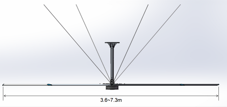
1.2.1 Fan diameter
1.2.2 Fan blade
5 pieces of high-efficiency streamlined fan blade design, reducing resistance to the minimum. The aviation aluminum alloy AA6005T5 is extruded and formed, and the surface is treated with special technology for durability and easy cleaning and maintenance.
1.2.3 Fan hub disc
Ultra high strength low alloy steel Q960D, Dynamic balance test after CNC precision machining, precise and reliable.
1.2.4 Drive components
The world's leading permanent magnet brushless motor, with energy efficiency standards reaching China's first level energy consumption, no gearbox, maintenance free, achieving ultra quiet operation of<40dB (A).
1.2.5 Control box
The independently developed control system has stepless speed regulation, overvoltage, overcurrent, phase failure, and overheating protection. The LCD touch screen can display the operating speed in real time.
1.2.6 Safety protection devices
(1) In the engineering design of permanent magnet industrial fans, multiple safety mechanisms are considered to prevent accidental falls of components or shaking caused by airflow. These protective devices can prevent damage to personnel or equipment. Please carefully follow the following instructions when installing the fan, such as the installation of the safety rope around the beam, otherwise it is not within the warranty period.
(2) L-shaped wing link buckles (5 pieces) need to connect each blade to adjacent blades to prevent the risk of single blade falling.
(3) Four 6mm hot-dip galvanized safety ropes are installed around the beam to prevent accidental failure and slipping of the fixing device for the large fan.
二. Safety essentials
Important safety instructions, please read and archive carefully!
Warning: To reduce the risk of fire, electric shock, or personal injury, please make sure to follow the following regulations:
2.1 Installation and electrical wiring must be carried out by personnel who comply with relevant national regulations and have obtained qualifications
Attention: The installation personnel must refer to this user manual and other relevant national standards to carry out the operation.
Warning: There is a high-voltage capacitor inside the fan variable frequency control box, and a certain discharge time is required when the main power is cut off.
Before checking the fan control, ensure that the power circuit breaker is disconnected, patiently wait for 3 minutes, and the inverter capacitor will discharge to a safe voltage before starting operation. Failure to comply with this requirement may cause personal injury or death.
Attention: Connect the fan power supply according to conventional electrical specifications, and check whether the voltage and grounding of the power supply are correct. Do not connect problematic or dangerous power supplies to the fan control box, and do not handle control faults without authorization. If there are any problems, please contact our after-sales service in a timely manner.
2.2 The fan must be installed with the original control box, and the components cannot be replaced arbitrarily.
Attention: When maintaining or replacing fan components, it is necessary to temporarily remove or disconnect the safety protection mechanisms of the fan itself. When reassembling, be sure to reinstall these mechanisms in their original positions.
Warning: To reduce the risk of fire, electric shock, or personal injury, please make sure to follow the following regulations
a) Please use the fan correctly according to the manufacturer's instructions. If there are any problems, please consult the manufacturer.
b) Before implementing fan inspection and maintenance, ensure that the power supply is isolated and locked with a warning sign to prevent accidental power connection during the maintenance process.
Attention: When installing, adjusting, or cleaning fan blades, do not bend them with external force, and do not place any objects between rotating fan blades.
Attention: Product damage caused by improper installation method will not be covered by our industrial fan warranty.
三. Preparation before installation
3.1 Confirmation of lifting method
Different types of building structures (I-shaped steel beams, concrete beams, or other requirements) require different special fixing brackets. Standard installation components are only suitable for I-shaped steel or concrete beam structures. If the building structure is different from the standard installation method, please consult a structural engineer to make special fixing components, which can be prefabricated in the factory.
(1) Check with the owner, contractor, or structural engineer to confirm if the building is fully capable of bearing or supporting the weight of the fan
(2) Confirm the elevation of the bottom of the building beam and the installation height of the fan
(3) Confirm the voltage level at which the installation site can provide power supply
3.2 Overall installation requirements
Attention: Inappropriate installation resulting in ineffective opening is not covered by the warranty
3.2.1 Weight
The weight of a standard fan with 5 blades and a maximum diameter of 7.3 meters is 89 kilograms. When the fan blows in the opposite direction, due to the forced push of the fan, an additional 20 kilograms of downward gravity will be transmitted. Typically, building structural beams can bear this weight; If you have any doubts, you can further consult a professional structural engineer for verification before purchasing.
Industrial fans can only be installed and fixed on the main structural beams of buildings (such as I-shaped steel beams, concrete structural beams, or angle steel structures). Do not fix and load the fan on a single purlin, corner brace, or support beam.
3.2.2 Torque
During the start-up process of the fan, the installation bracket will generate the maximum tangential torque. For a standard 7.3 meter diameter fan, the maximum possible start-up torque value is 220N · m. Our electrical control system adopts soft start technology to avoid the maximum torque during the start-up process. But in case of soft start failure, it is still possible, so when installing the bracket, we need to fully consider bearing a torque of 220N · m, which is also very important.
3.2.3 Safety Rope Around Beam
Considering the risk of the fan falling off, regardless of the installation method of the suspended fan, safety ropes should be considered.
The safety rope and fixing clip will be supplied together with the fan. The fan is not allowed to operate without a safety rope. Please refer to Figure 3.1 to correctly install the safety rope.
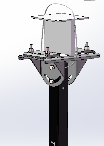
Figure 3.1
3.2.4 Safety clearance and traction fixing cables
Space requirements need to consider the possibility of collisions caused by fan oscillation. Due to the possibility of slight oscillation during fan operation, any spacing needs to be greater than 0.3m. The running fan may sway due to minor imbalances or the influence of wind, so the traction wire cable must be installed correctly.
3.3 Installation positioning
The fan must be installed at a height of 3 meters above the ground. Fans should not be installed too close to the roof or ceiling to avoid insufficient air circulation. The height of the fan from the roof should not be less than 15% of the fan diameter. If the roof has a certain slope and the fan blades are slightly closer to the roof on one side, as long as there is sufficient open area on the other side.
Ⅳ. Installation steps and methods of fan structural components
4.1 Equipment Room Connection
There are two standard installation methods for connecting fans to the factory building.
(1) Connected to I-shaped steel beams: With an adjustable standard clamping device, the equipment can be easily clamped onto any I-shaped steel beam without the need to modify any steel beam.
(2) Connection with cement beam: The standard connection device is fixed on the cement beam by bolts, and the connection device can be adjusted according to the width of the beam to meet the needs of different sizes of cement beams.
4.2 Installation of ceiling components
For drainage purposes, roofs are usually sloped and have varying degrees of inclination. Therefore, our installation components are adjusted in direction through waist holes, allowing fans to be positioned in all four directions regardless of the slope of the roof, as shown in Figure 4.1.
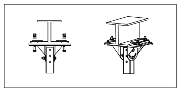
Figure 4.1 Installation of ceiling components
4.3 Installation of Motor
The fan is already installed as a whole before leaving the factory, and can be fixed as a whole on the extension rod by bolts.
4.4 Layout of Electrical Conduits and Wiring
(1) The wire conduit is arranged along the pillars of the factory building, and the top is arranged along the structural steel beam without any obvious protrusion.
(2) Arrange the conduit as short as possible and keep the wiring as simple as possible;
(3) Before wiring, please make sure to disconnect the power supply and connect the wires on the motor before connecting the wires on the electrical control box.
4.5 Installation of balanced steel wire rope
Each fan has four uniformly distributed steel wire ropes that are tightened, and the angle between each steel wire rope and the driving device should be kept at around 45 ° as much as possible. If it is too large or too small, it will affect the effectiveness of the steel wire rope. The main functions of steel wire ropes are as follows:
(1) Reduce the shaking of the fan during operation;
(2) The steel wire rope ensures the level of the fan chassis and improves the dynamic balance of the fan;
(3) A safety protection device to prevent the driving device from falling.
4.6 Assemble the propeller blades to the installed hub
(1) Warning: Make sure to disconnect the power before installing the fan blades.
(2) Carefully insert the blade with the installed fan blade end cover into the fan blade installation plate, and it is strictly prohibited to forcefully insert it with external force. Referring to Figure 4.2 can ensure that you install the blades correctly (the blades can only be installed in one direction).
(3) Align the bolt holes on the fan blade with the bolt holes on the fan blade mounting plate.
(4) Place the 5 safety links of the fan blades in order, align and overlap the empty spaces as shown in Figure 4.2, and then place the bolt fasteners. Do not tighten the bolts before all connectors are fully placed and aligned.
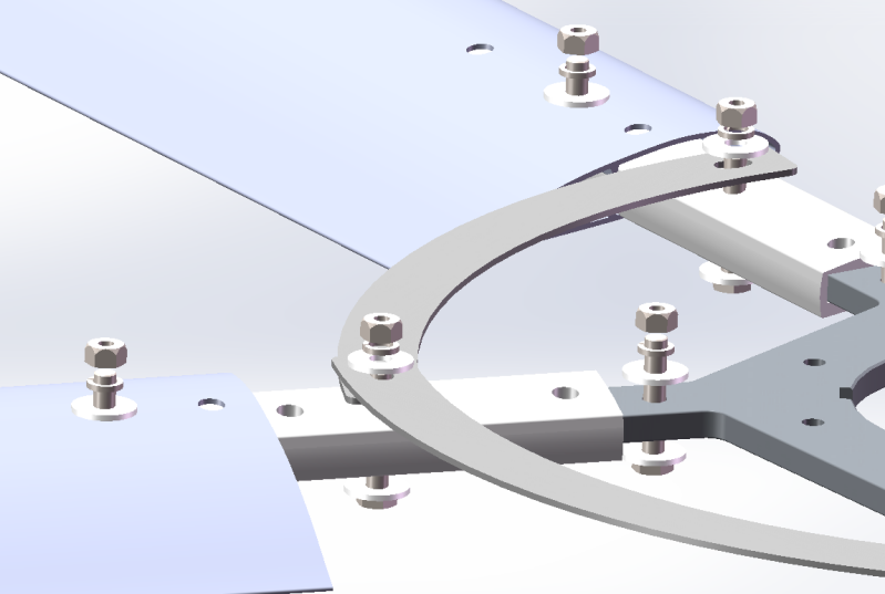
Figure 4.2
Firstly, use a socket tool to tighten the outer ring bolts in sequence, with a tightening force of 39N · m.
Then use a socket tool to tighten the inner ring bolts in sequence, with a tightening force of 39N · m.
Attention: When installing, adjusting, and cleaning fan blades, do not bend the blades, and do not insert any objects between rotating fan blades!
4.7 Installation of Bottom Cover Logo
Close the chassis to the hub of the fan blade, align it with the bolt holes, and tighten it with bolts. There should be no missing or loose fastening, and the bottom cover should not shake after installation.
4.8 Specification parameter table
|
MODEL
|
Diameter
M
|
Number of blades
PCS
|
Weight
Kg
|
Voltage
|
Current
A
|
Power
kW
|
Maximum speed
RPM
|
Maximum air volume
㎥/min
|
|
TIF-7L |
7.3 |
5 |
89 |
220/380 |
4.8 |
1.20 |
60 |
14500 |
|
TIF-6L |
6.1 |
5 |
80 |
220/380 |
4.6 |
1.10 |
70 |
13200 |
|
TIF-5L |
5.5 |
5 |
75 |
220/380 |
4.3 |
1.0 |
80 |
12200 |
|
TIF-4L |
4.8 |
5 |
70 |
220/380 |
4.1 |
0.9 |
90 |
10800 |
|
TIF-3L |
3.6 |
5 |
60 |
220/380 |
2.4 |
0.5 |
100 |
8800 |
Ⅴ. Electrical installation
5.1 Control box configuration
5.2 Wiring
5.2.1 General
Variable frequency drive may generate induced voltage that damages the motor, as well as harmonic interference or radio frequency interference that may affect other low-voltage electrical control facilities. The following principles must also be followed during installation and wiring.
(1) Under 380V voltage input, the length of the cable conduit between the control box and the fan shall not exceed 30 meters, and under 220V voltage, it shall not exceed 40 meters. Excessive distance will amplify the voltage surge generated by the variable frequency drive.
(2) Do not use cables that are much larger than the specifications allow, as excessively large wire diameters can also amplify voltage surges.
(3) The wiring of each fan needs to be laid separately with a grounding metal conduit. Do not tie multiple cables together and enter the control box, or pass the wiring through other fans. During the wiring process, a section of flexible conduit needs to be installed at the end to allow for minimal movement of the fan.
(4) Ensure that the control box outlet must use 4-core wires: 3 phase wires and 1 ground wire.
(5) Alternatively, a 4-core shielded cable should also be used with good grounding to avoid forming a loop between the grounding wire and the ground, which could weaken the grounding effect.
(6) The parallel laying distance between the output lines of each fan shall not be less than 150mm.
5.2.2 Grounding
A separate grounding wire must be installed between the motor and the control box.
5.2.3 Motor wiring
The motor must be wired correctly according to the voltage you are using, and it is also necessary to check whether the frequency converter device matches the voltage you provide correctly.
The correct rotation direction of the fan blades should be as shown in Figure 5.1. If the fan is started in the wrong direction for the first time, it should be stopped immediately and the power should be cut off. Simply replace any two phase wires, and the rotation direction of the motor will be reversed. The wire replacement can be done on both the motor side and the control box side.
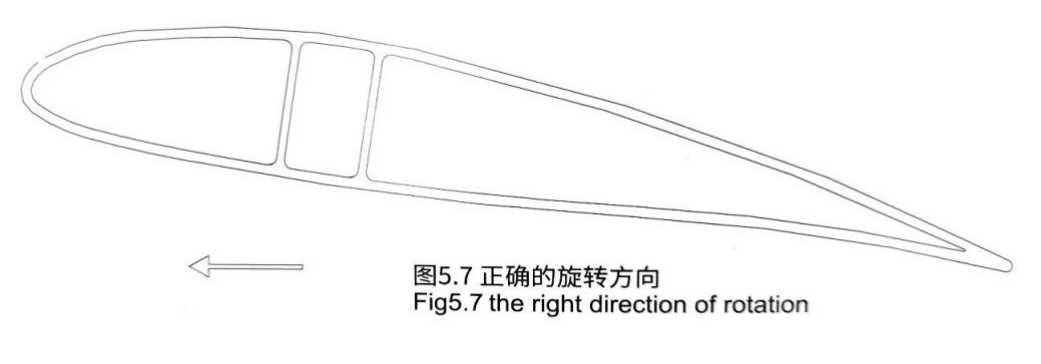
Figure 5.1 Correct rotation direction
Ⅵ. Fixed cable settings for fans
6.1 Principles of Cable Installation
Any fan may experience local oscillation due to external wind force and its own airflow, so fixed cables need to be installed.
Please follow the following principles to install the cable:
a) Set up fixing cables before installing the fan blades.
b) Each fan uses 4 steel wire ropes, and each cable is equipped with 4 clips (two fixed at each end).
c) Do not bend the steel wire rope excessively, it cannot be used when bent beyond 45 degrees.
d) Fix one end of the steel wire rope to the building structure, and connect the other end to the main frame with a floral screw.
Attention: It is very important to avoid winding the steel wire rope into some sharp corners. Although the external force used to stabilize the fan is very small, a continuously rotating fan, even if very slight, may eventually cause fatigue damage to the steel wire rope in areas with severe curling.
e) We recommend installing the steel wire rope in the following order:
(1) First connect the steel wire rope to the building structure, install two clamps on each rope, and then lock it.
(2) Fix the other end of the steel wire rope in the hook of the fan motor, install two rope clamps, tighten the rope and fix the clamp, first fix the one far away from the fan.
(3) Implement the steel wire rope tensioning work again, ensuring that the fan motor remains naturally vertical and horizontal during the tensioning process. Adjust the four steel wire ropes repeatedly until the elasticity is consistent, and then lock the proximal steel wire rope clamp.
Attention: The key is to ensure that all ropes have a uniform and consistent degree of tightness at the beginning.
(4) Finally, loosen the outermost clip, tighten the loose part, and tighten the proximal clip again to ensure that both clips are in a locked state.
Ⅶ. Operating steps for turning on the industrial fan
■ After powering on, press the touch screen power button.
■ Increase/decrease the operating speed as needed.
■ The fan starts to slowly accelerate.
■ Verify the rotation of the fan in the forward position, and the fan blades should rotate counterclockwise when viewed from the ground.